A key contributor to this effort is Woodknowledge Wales (WKW), whose deep commitment to building a sustainable, low-carbon future has shaped both the content and direction of this Yearbook. Led by Sarah Lawton, an editor and communicator working to connect the timber industry with the wider climate, land-use and design agenda, the WKW team has played a central role in curating the insights, case studies, and technical contributions you'll find in these pages.
Engineering reliable interfaces in offsite timber construction
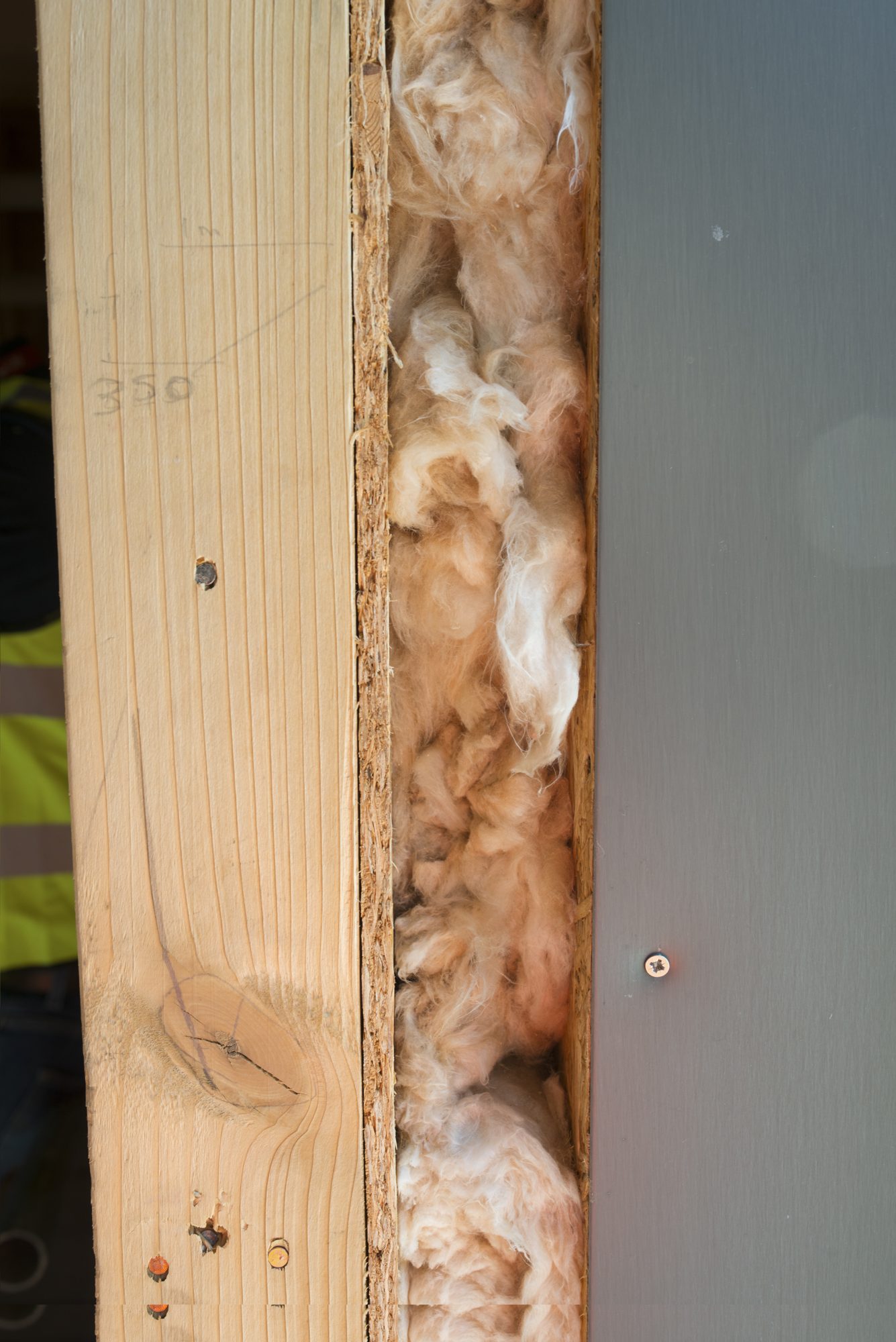
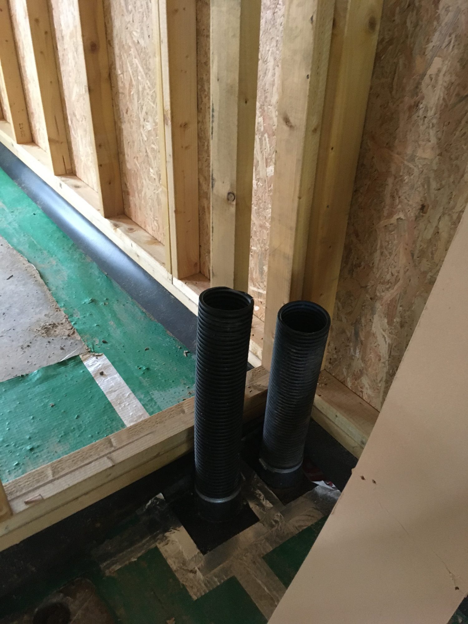
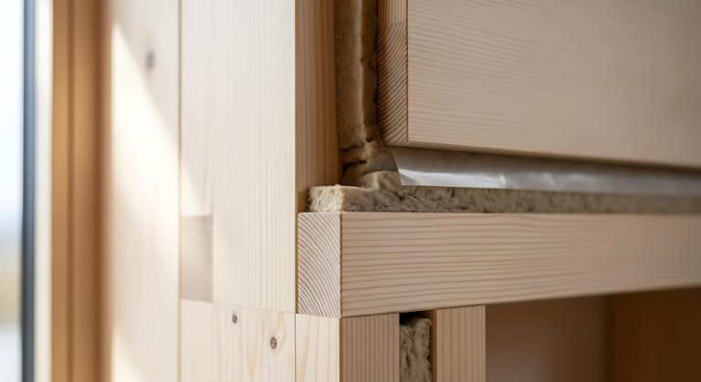
Factory manufacture can improve consistency and accuracy, but the completed performance of an offsite timber building depends on what happens where panels, structures, façades, services and site-built elements meet. Reliable delivery requires these interfaces to be designed as multi-performance details—not treated simply as connections between components.
Offsite timber construction is frequently discussed in terms of the components produced: wall panels, floor cassettes, roof elements, structural frames and volumetric modules. Yet buildings do not perform as a collection of isolated products. Their structural, environmental and life-safety performance must continue across the junctions where those products meet each other and the rest of the building.
These interfaces can be physical, such as the connection between a wall panel and floor cassette, or organisational, where responsibility passes between designers, manufacturers and site contractors. In practice, the two are closely related. A junction may be accurately manufactured yet remain vulnerable if the adjoining construction has not been coordinated, tolerances are incompatible or responsibility for completing the detail is unclear.
This matters as timber construction expands through modern methods of construction. The Government’s Timber in Construction Roadmap 2025 identifies offsite-manufactured open- and closed-panel timber frames as the most established structural timber systems in England. It also identifies safe application, technical competence, fire safety, durability and engagement with insurers, lenders and warranty providers as important conditions for wider adoption.¹
Reliable interfaces sit at the centre of that challenge. Factory conditions can support repeatable production, but they do not remove the foundations, façades, roofs, services and finishing trades that must connect with manufactured elements onsite.
Managing loads, movement and tolerances
At its most visible, an interface provides a load path. Connections between panels, floors, roofs and foundations may need to transfer vertical loads, shear, uplift, overturning forces and diaphragm actions. Their performance depends not only on the calculated capacity of a fastener or bracket, but also on bearing conditions, edge distances, timber condition, restraint and installation accuracy.
The junction must also accommodate movement. Timber components undergo moisture-related dimensional movement, while adjoining concrete, masonry and steel elements have different movement, settlement and deformation characteristics. Differential settlement, compression and dimensional variation can affect cladding, finishes, seals and service connections even where the primary structural design remains adequate.
This makes tolerance management a fundamental part of interface design. An accurately manufactured timber panel may still arrive at a slab edge, steel frame or façade zone constructed within a different tolerance regime. The objective is not to assume perfect alignment but to establish how the detail will perform when adjoining elements are at the permitted limits of variation.
Allowance may be needed for adjustment, bearing, seal compression or fixing position. These provisions must be designed rather than improvised during installation. Factory accuracy is valuable, but accuracy within one package cannot compensate for an undefined or incompatible tolerance at the adjoining package.
Where performance is won—or lost
The most demanding interfaces are rarely required to perform one function. A wall-to-floor junction, for example, may need to transfer structural loads while maintaining airtightness, insulation continuity, acoustic separation, fire stopping and protection against moisture. Each requirement may be addressed by a different designer, specialist contractor or product supplier, yet all must occupy the same physical space.
Fire safety demonstrates the importance of that coordination. The Structural Timber Association identifies numerous locations where cavity barriers and fire stopping interact with other building systems, including floor-to-wall, roof-to-wall, compartment-wall and external-façade junctions, together with openings and service penetrations. Its guidance places the determination of cavity-barrier requirements within the project fire-safety strategy and stresses that responsibility for design, supply, installation and interfaces must be clearly agreed. It should not simply be assumed that the timber-frame supplier has resolved every building-wide junction.²
A detail that appears workable in isolation may therefore become compromised when the façade support, membrane, floor zone or service route is added. Installation sequence and access must be considered alongside the specified product. A fire-stopping arrangement cannot be relied upon if it becomes inaccessible before it has been completed and inspected.
Airtightness presents a similar coordination problem. Passivhaus Trust guidance recommends identifying a continuous air barrier on plans and sections, while recognising that the installed layer must work in three dimensions.³ The line may need to pass around windows and doors, behind intermediate floors, across party-wall junctions and through transitions between factory-installed and site-applied materials.
Although tapes, membranes and airtight boards can support this strategy, their effectiveness depends on substrates, geometry, laps, access and workmanship. An air barrier that cannot be traced continuously through the junction is unlikely to be made reliable simply by adding sealant onsite.
Thermal performance is also influenced by the interface. Conductive components can create thermal bridges, while gaps or connected cavities can allow air movement that bypasses insulation. Passivhaus Trust research into thermal bypass highlights the risks created by air gaps, connected air paths and poorly resolved wall, floor and roof junctions.⁴ The nominal performance of the insulation product may therefore differ from the performance achieved by the assembled envelope.
Acoustics add another layer. Sound can bypass a separating wall or floor through adjoining façades, internal walls, foundations and structural junctions. Robust Details guidance consequently treats flanking conditions as part of the tested or assessed construction rather than as secondary work.⁵ A substituted board, altered closer, continuous structural member or poorly sealed junction can change a flanking path or take the construction outside the tested or registered configuration.
These examples underline a wider point: component compliance does not by itself demonstrate whole-building performance. The relevant question is not simply whether each product meets its own requirement, but whether the completed assembly preserves all required functions where systems intersect.
Moisture and durability at transitions
Moisture risk also tends to concentrate at transitions: sole plates, panel bases, roof edges, openings, penetrations and junctions between timber and wet construction. These are locations where water-shedding, drainage, vapour control and drying strategies may change between materials or trade packages.
Offsite manufacture can protect elements during production, but transport, storage and erection introduce temporary exposure. Connections may also create pockets in which water can collect or areas that become inaccessible after the next stage of assembly.
The design should therefore establish how water will be excluded or drained, how affected materials can dry, and what verified moisture condition must be achieved before the interface is enclosed. Temporary protection should connect logically with the permanent weathering strategy rather than being treated as a separate site measure.
Responsibility is particularly important at openings and façade junctions. The frame manufacturer may form the opening, another supplier may provide the window, and separate contractors may install membranes, cavity barriers and external finishes. Unless the completed detail is coordinated, each package may be individually correct while the transition between them remains unresolved.
Designing for manufacture and assembly
Design for manufacture and assembly is sometimes interpreted primarily as the rationalisation of components for factory production. For interfaces, it must also address the practical conditions under which those components will be positioned, connected, sealed and inspected.
The design team should understand from which side a fixing can be installed, whether tools and operatives will have sufficient access and what happens after the next panel or lining is placed. The sequence must allow membranes, seals, cavity barriers and fire stopping to be completed without obstructing structural installation or exposing finished work to unnecessary damage.
Lifting and transport conditions may also influence the interface. Factory-installed windows, cladding supports, membranes or services must withstand handling and movement before the building reaches its permanent condition. Temporary restraint and weather protection should be coordinated with the final connection rather than compete for the same space.
Government research into volumetric modular construction identifies the boundary between factory and site as a recurring area of technical and regulatory risk. Although volumetric construction differs from panelised timber systems, the wider lesson is relevant: offsite delivery depends upon early design decisions, integrated project teams and clear ownership of factory-to-site interfaces.⁶
Designing a component for manufacture is therefore only part of the task. The adjoining team must also be able to position, connect, seal, inspect and record it under real site conditions.
Delivering interface quality consistently
Reliable interfaces require more than a coordinated drawing. They need an agreed process through which design intent can be checked as work passes between organisations and locations.
A project may use interface schedules, responsibility matrices, coordinated three-dimensional details and tolerance strategies to define what is required. Prototype or benchmark assemblies can test whether critical junctions are buildable before they are repeated across the project.
Inspection points should reflect the installation sequence. Photographic records, moisture checks, fixing inspections and sign-off procedures are most useful before critical work becomes concealed. Where an onsite condition differs from the approved detail, the response should be designed, authorised and recorded rather than treated as an informal adjustment.
This evidence must follow the interface across the factory/site boundary. A manufacturing record cannot confirm work subsequently completed onsite, while a site photograph may not establish what lies within a closed panel. Together, however, proportionate records can demonstrate how the completed junction corresponds with the approved design.
The central commercial issue is ownership. Interfaces frequently lie between the architect, structural engineer, fire engineer, timber-system designer, façade designer, services consultant, manufacturer and main contractor. Coordination cannot depend upon each party assuming that another has resolved the gap.
An interface without clearly allocated design responsibility is not a coordinated detail; it is an assumption shared between contracts.
As offsite timber systems become more sophisticated, the quality of the manufactured component will remain important. However, the completed building will be judged by whether loads, compartment lines, environmental layers and finishes continue to perform when those components come together. Reliable timber construction depends on treating every critical interface as part of the engineered building—not as the space left between individual packages.
References
Department for Environment, Food & Rural Affairs, Timber in Construction Roadmap 2025, March 2025.
Structural Timber Association, Structural Timber Buildings Fire Safety in Use: Cavity Barriers and Fire Stopping, Volume 2, Version 3.1, January 2025.
Passivhaus Trust, Good Practice Guide to Airtightness, Version 10.4.
Passivhaus Trust, Thermal Bypass Risks: A Technical Review, Version 1.0.
Robust Details Limited, Robust Details Handbook: Part E—Resistance to the Passage of Sound, Fourth Edition, including April 2026 update.
Department for Levelling Up, Housing and Communities, Volumetric Modular Construction Research, 2023.
To provide the best experiences, we use technologies like cookies to store and/or access device information. Consenting to these technologies will allow us to process data such as browsing behavior or unique IDs on this site. Not consenting or withdrawing consent, may adversely affect certain features and functions.
Functional
Always active
The technical storage or access is strictly necessary for the legitimate purpose of enabling the use of a specific service explicitly requested by the subscriber or user, or for the sole purpose of carrying out the transmission of a communication over an electronic communications network.
Preferences
The technical storage or access is necessary for the legitimate purpose of storing preferences that are not requested by the subscriber or user.
Statistics
The technical storage or access that is used exclusively for statistical purposes.The technical storage or access that is used exclusively for anonymous statistical purposes. Without a subpoena, voluntary compliance on the part of your Internet Service Provider, or additional records from a third party, information stored or retrieved for this purpose alone cannot usually be used to identify you.
Marketing
The technical storage or access is required to create user profiles to send advertising, or to track the user on a website or across several websites for similar marketing purposes.